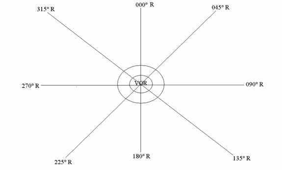
VOR operates on Frequency band of 108-118 MHz. In the Frequency band of 108-112 MHz, it shares Frequency with the ILS system, The ILS operates on Odd Decimals, and VOR operates on Even Decimals, the Frequency band of 112- 118 MHz is allocated to VOR with Even and Odd both decimals.
VOR has two aerial, the principle used is Phase Difference.
- Constant Phase Aerial- it has constant phase in 360° plane. It transmits on 30 Hz, Amplitude Modulation.
- Fixed Phase Aerial- it transmits on 30 Hz, Frequency Modulation.
It removes the ambiguity of two minima and two maxima caused by the Constant Phase Aerial.
At 000°/ North direction the Phase difference is zero between both signals,
On combining the Constant Phase Aerial and Variable Phase Aerial we get a heart shaped figure called LIMACON.
The difference between CARDIOID and LIMACON is that CARDIOID has an absolute null position, whereas a LIMACON still has some energy at its minimum position, Therefore the LIMACON has no absolute null position as a CARDIOID.
The main equipment of VOR Transmitter is located on the ground and the a/c only has the receiver that receives the Radio Waves and displays the same as Radials on the VOR Indicator. Unlike ADF which has the main Transmitter located in the A/c and ground equipment only has a receiver.
For this reason the Magnetic Variation if applicable is applied to the VOR transmitter located on the ground, since it has the Transmitter located on the ground.
In case of ADF the Magnetic Variation if applicable is applied to the A/c position since it has the Transmitter located in the A/c.
A cone of confusion occurs exactly overhead the facility, since the beams are tilted at an angle of 70-80° from the horizontal plane.
The range of VOR depends upon the range of VHF waves, which depends upon the line of sight.
This can be calculated by using the formulae-
RANGE = 1.25 √Height of A/c + 1.25 √Height of Transmitter
A VOR can be considered to be a Radio Aid that is radiating radio waves in 360° in a horizontal plane in all directions, called RADIALS.

A/c equipment has a VOR indicator that ranges from 4 dot indicator to 5 dot indicator also called Course Deviation Indicator and an Omni Bearing Selector, which is used to set the required RADIAL into the window.
To/From indicator will be shown, depending upon whether is flying towards or away from the facility.
A Failure Flag is also installed in the system which comes up to show unreliable signals, caused by failure of Radio Aid or A/c equipment unserviceable or when the signals received exceed the max tolerated error.
VOT- is a term called for VOR Transmitters specially designed for testing the VOR equipment. It is checked for the accuracy during Pre-Flight Check, and is with in the acceptable limits if the error does not exceed ± 4°. This error is allowed since the Beam width of VOR signal is 4°, therefore we can also say that there are 90 beams coming out of the VOR station, instead of 360.
Example- 360 ÷ 4= 90.
VOR full scale deflection causes 10° deflection on either side of Course Deviation Indicator.
VOR 1 dot deflection in a 5 dot indicator causes a/c to be 200 feet away from the selected radial every 1 N.M from the Ground facility.
Example-
1 A/c is at a distance of 60 N.M and VOR indicator is showing 1 dot away (on a 5 dot Indicator)
On calculating by one in sixty rule we get
Where 1 N.M is taken as 6080 feet.
200 is the distance the A/c is away on every 1 dot deflection from the selected radial
1 is the dot deflection of the A/c from its selected radial
60 is the distance the A/c is away from the facility
200 ×1 × 60 ÷ 6080 = 1.97 or 2 N.M
Therefore the A/c is 2 N.M away from the selected radial
1 A/c is at a distance of 30 N.M and VOR indicator is showing 2 dot away from the selected radial (on a 4 dot indicator)
On calculating by one in sixty rule we get
1 N.M. is taken as 6080 feet
250 is the distance the A/c is away on every I dot deflection from the selected radial
2 is the dot deflection of the A/c from its selected radial
30 is the distance the A/c is away from the facility
250 ×2 × 30 ÷ 6080 = 2.46 or 2.5 N.M
Errors-
- Site Error- the high terrain in he surrounding area of navigation facility causes range to be effected.
- Interference Error- the interference caused by the obstructions between the Transmitter and Receiver causes error in the reception.
- Pilot Error- caused by wrong interpretation of signals by the Pilot.
- Propagation error- is caused by the uneven terrain and other features that cause the signal to be affected until it reaches the receiver.
- Airborne Equipment Error- caused by the faulty equipment in the cockpit.
DOPPLER VOR
Doppler VOR has one fixed aerial surrounded by 50 aerials
Fixed Aerial- is located in the centre. It transmits on 30 Hz, Amplitude Modulation.
50 Variable Phase Aerial- are located around the Fixed Aerial and transmits on 30 Hz, Frequency Modulation.
They remove the ambiguity of two minima and two maxima caused by the Constant Phase Aerial.
The benefit of the DVOR is that it can be located at the Airfield, since it does not suffer from the Site Error of conventional VOR.
