Wing Loading= Gross Weight ÷ Wing Area
Span Loading = Gross Weight ÷ Wing Span
Load Factor = Lift ÷ Weight
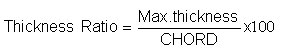
An Aerofoil is specified by its Thickness Ratio
It is also defined as the percentage of the Chord.
Thickness Ratio = Thickness Max ÷ Chord × 100
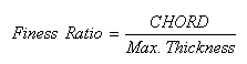
Drag of an Aerofoil depends upon Fineness Ratio.
It is the ratio of Length/ Chord to maximum Diameter.
Fineness Ratio = Chord ÷ Thickness × 100
As Fineness Ratio increases Induced Ratio decreases.
Dorsal fin – increases the directional stability and lateral stability.
Vendral fin – increases directional stability.
HIGH KEEL SURFACE– is that part of the vertical stabilizer which assists in the directional stability. It is the fin area above the C.G. point.
KEEL SURFACE/ LOW KEEL SURFACE – is the area below the C.G. point.
RATE OF CLIMB– is the height gained by an Aircraft over the time.
ANGLE OF CLIMB- is the height gained by an Aircraft over a given distance.
CLIMB GRADIENT- is calculated using True Air Speed and Rate of Climb.
FLIGHT PATH GRADIENT– is calculated using Ground Speed and the Rate of Climb
Weight increases Gliding Endurance decreases.
Weight decreases Gliding Endurance increases.
Weight has no effect on gliding range or gliding angle provided best Lift/Drag ratio speed is maintained.
When Weight increases best Lift/Drag speed also increases.
At higher Altitude, Gliding Range increases, because at higher altitude the True Air Speed increases.
Angle of Climb is governed by Thrust.
Rate of Climb is governed by Power.
Velocity of minimum power is slightly less than velocity of minimum drag.
During Preflight Inspection if control column is moved—
SERVO TAB– Control surface don’t move, tab moves
SPRING TAB– Control surface moves, but tab don’t move, also called High Speed Tab
BALANCE TAB– Decreases force required by the Pilot to move controls, move opposite to controls, also called Low Speed Tab
HORN BALANCE/MASS BALANCE– reduces force required by pilot to move controls
Active Ailerons – is an Autopilot function. The Autopilot when engaged deflects both the ailerons simultaneously upwards to relieve the loads caused by the high gusts and reduce wing bending moments, which is more prominent in Sweepback wing A/c.
Ventral Stakes – are located on Vertical Stabilizer (FIN) in the horizontal directions as thin plates.
They help stall recovery at high altitudes, and at high angles of attack, when A/c loses all Elevator movement.
They are located on Cessna Citation Excel and the Newest XLS.
Minimum Drag Speed gives best Rate of Climb, since the A/c climbs because of Excess Thrust. Excess Thrust is Maximum only when the Drag produced is Minimum. Therefore for best Rate of Climb, the difference between Thrust and Drag should be Maximum.
If the Centre of Gravity is located too Rearward the rudder becomes In-effective, due to decrease moment between the rudder arm and the C.G position, causing VMC to increase, since in the case of a engine failure, the rudder movement is less and restoring forces are reduced.
If the Centre of Gravity is located too forward the rudder becomes more effective, due to increase moment between the rudder arm and the C.G position, causing VMC to decrease, since in the case of engine failure, the rudder movement is more and restoring forces are increased.
For Stability – If the Centre of Gravity is located too forward the A/c becomes more stable and less controllable in Longitudinal Axis, and will require larger control inputs for a maneuver.
For Stability- If the Centre of Gravity is located too rearward the A/c becomes less stable and more controllable in Longitudinal Axis, and will require lesser control inputs for a maneuver.
At high altitude operating conditions where the A/c engine can not produce high amount of Thrust at high altitudes, due to low density of air, the VMC reduces.
At low altitude operating conditions where the A/c engine can produce high amount of Thrust at low altitudes, due to high density of air, the VMC increases.
In summer weather conditions, due to low density of air, the A/c engine can not produce high Thrust, the VMC reduces.
In winter weather conditions, due to high density of air, the A/c engine can produce high Thrust, the VMC increases.
The effect of engine failure is more in a Dihedral wing A/c, because it has more Lateral Stability, which causes it to yaw when rolled, causing a further roll movement.
Touch down Elevation– is the highest elevation in the first 3000 feet of the landing surface.
Compressibility is a function of speed of sound as speed of sound increases, compressibility decreases.
As altitude increases, speed of sound decreases, compressibility error increases.
Critical Mach No. – is the Mach No. at which A/c stability and Controllability are adversely affected due to on setting of the Shock Waves at some point on the A/c structure.
Limiting Mach No. – is the Mach. No. above which stability and controllability of A/c are adversely affected.
Limiting Mach No. is much higher than Critical Mach No.
When A/c is flying above Critical Mach No. /Limiting Mach No.
It experiences
- Coefficient of Lift decrease significantly.
- Coefficient of Drag increases significantly.
MCRD- Drag Rise Mach No. or Critical Drag Mach No.
The combined effect of the energy losses due to dissipation of energy and formation of shock wave is called Wave Drag.
At the speeds just above MCRIT (MCRIT- Critical Mach No.), drag is due to dissipation of energy due to wave friction and is quiet small, but it increases significantly as the speed is increased.
At speeds above MCRIT the on setting shock waves causes Boundary layer above the wing to separate from the wing completely, causing CL to decrease and CD to increase significantly.
Disturbed airflow is caused by the energy dissipation due to formation of shock waves.
High Speed Roll- occurs at high speed because of the dampened airflow caused by the difference in wing structure, (due to dents on the wing, or due to very minor difference in the construction of the wings which is not visible to the naked eye, but is more significant at high speeds).
It causes the separation of the airflow behind the shock waves causing the Centre of Pressure of the wing to go forward and cause nose up pitching moment as well as a rolling moment due to early formation of shock waves on one wing.
Aileron Snapping- occurs at high speed, when the formation of shock waves, causes the Boundary layer to be detached and connect to the aerofoil of the A/c, causing high speed Aileron movement about its mean position.
Wing Twist- occurs at high speed flight. It occurs in Sweepback wing A/c, which are weaker towards tip than at roots, giving aerodynamic warning to the pilot that the speed should be decreased to avoid structural failure or the wing to break.
The speed should be reduced by decreasing Throttle or by using spoilers as speed brakes to avoid exceeding A/c structure limitations.
A/c Buffeting- occurs at high speed flight. It occurs as the turbulent airflow caused by the shockwaves hits the Control surfaces and disturbs its streamline flow pattern, causing the A/c to oscillate in Longitudinal Axis, Neutral Axis as well as Lateral Axis.
Mach Tuck/Tuck Under- occurs at high speed flight. It occurs as the A/c exceeds a specified speed limit, above which the Elevator loses its effectiveness due to being exposed to disturbed airflow.
This occurs since in the normal flight the A/c horizontal stabilizer divides the airflow into two, one flowing downward from the above, and another flowing upward from the below, following the stabilizer surface. When the A/c speed exceeds a specified limit, the downwash coming above the stabilizer decreases, causing the stabilizer to lose its effectiveness. This situation is further aggravated by the on setting of the shock waves, which causes disturbed airflow to hit the tail plane, decreasing its effectiveness further.
The shock waves formed over the wing proceeds rearward as the speed increases, causes Centre of Pressure to move rearward as well, further increasing the nose down pitch moment.
The A/c loses longitudinal stability due to ineffective elevator.
This is more prominent at high altitude, where low density of air enhances acceleration as compared to high density of air found at low altitude.
To recover, the speed must be decreased by decreasing Throttle or increasing the Nose angle, any delay in the action will cause A/c to be in a dangerously uncontrollable dive.
Auto Recovery of Tuck Up- can be termed as later characteristics of Mach Tuck phenomenon.
This occurs when the A/c is in a dive, and elevator is fully deflected in up position to give a nose up moment, and A/c is in a dive of a high angle, a point is reached when the turbulent airflow over the tail plane causes the tail to produce abrupt nose up moment. This abrupt movement can cause a substantial damage to the A/c tail plane or can even cause total structural failure.
Therefore the best way is to avoid the on setting of Mach tuck Phenomenon.
QUIET CLIMB SYSTEM- is a system incorporated in the Autopilot which on being engaged automatically senses when the A/c is flying over a Noise Sensitive Area and reduces the Throttle setting with in specified limits according to A/c performance tables to control engine sound in Noise sensitive Area procedure. It calculates the A/c position by comparing the GPS derived position along with the position calculated by the FMS system to calculate the Noise Sensitive Area.
VERTICAL SITUATION DISPLAY- is a display system that shows the terrain information of the surrounding area, along with the descent profile of the A/c in relation to the obstacles.
Air conditioning can be used for cooling but Air Conditioning increases empty weight of the aero plane & requires power from the engine. Some equipments/systems also increase drag because the condenser or a scoop is exposed to the slipstream flow and decreases the A/c Performance.
That’s why Air conditioner is usually off for Take off and landing.
Therefore, there is a decrease in TAS with air conditioning & Range decreases.
On a symmetrical aerofoil as angle of attack is changed, the C.P. remains constant.
If an Inclinometer (Rate of Turn Indicator) is mounted on the left side of the instrument panel, the ball will be displaced to the left in a spin, regardless of the direction of the spin.
TECHNICAL
Fin & Tail plane is called Emphennage.
Monocoque Structure – (Like an egg) – There are no internal bracings or support.
Semi-Monocoque – Round rings which are called frames or bulkheads.
They are joined with the longitudinal base called Longerons & Stringers.
Longerons & Stringers are longitudinal members of the fuselage. They increase strength of the fuselage.
Spars are lateral members of the wing.
The spars are buried deep into the fuselage.
Ribs are longitudinal members of the wing. They give aerofoil shape to the wings.
Wings may have one or two spars but many stringers. Once we get the shape we cover it with the skin.
Fuselage is Truss type construction.
A number of hollow tubes are put together.
Gussets – are metal plates joined to the Truss. They increase strength of the Truss.
Cantilever wing – has no external support.
Semi-Cantilever wing – has external support like Struts.
External bracing below the wings are called STRUTS.
Chord line – is a straight line joining the leading edge & the trailing edge of the Aerofoil.
Camber line – is an equidistant line from top & bottom surface of the Aerofoil.
Camber – is distance between the Mean Camber line & the Chord line.
Camber – is also defined as the curvature of top and bottom surface of the aerofoil.
Thickness is distance between the top & bottom surface of the Aerofoil.
Thickness Ratio = 
Finess Ratio =
Angle of attack – is a acute angle (less than 90o) which the chord makes with rel. airflows.
70% of lift is produced from above the wing.
30% of lift is produced from below the wing.
Stagnation point – Air comes to a complete halt at the leading edge of an Aerofoil.
At Stagnation point the velocity is zero & the pressure is maximum.
Stagnation point
Total Reaction depends upon following
- Air density
- Velocity of a/c
- Surface area of wing
- Shape of Aerofoil
- Angle of attack
Total pressure is tilted backward & is perpendicular to the chord line.
Total Reaction can be divided into 2 parts.
Lift = Lift is vertical component of Total reaction.
Lift = ½ ℓV2 S CL.
ℓ = Air Density
V = Velocity (Airspeed)
S = Surface Area
CL = Co-eff. of Lift
Co-efficient of Lift depends upon
1) Shape of the Aerofoil.
2) Angle of attack
In a particular A/c, the shape of aerofoil remains the same therefore lift will depend on angle of attack.
As angle of attack increases lift increases.
At Critical Angle lift is maximum, after which it decreases & will not be able to support the weight of the A/c in air & A/c will start loosing hright. This condition is known as STALL.
Drag is horizontal component of Total Reaction.
Drag is the resistance offered by the A/c to the airflow
Drag = ½ ℓv2S CD.
CD = Co-efficient of drag, which depends on
(a) Shape of Aerofoil
(b) Angle of attack.
Propeller converts mechanical energy of engine into forward thrust.
Connecting Rod is also known as Shank.

Normal flame rate in piston engine ignition is 50 to 80 seconds.
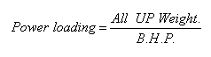
Mechanical Efficiency is ratio between Brake horse power and Indicated horse power.
A/c engines are heat engines they convert heat energy into mechanical energy.
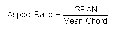
Taper Ratio – is ratio between the Tip chord & Root chord.
SPAN loading – is ratio between All up weight & wing span.
Wing loading – is ratio between All up weight & wing area
Distness frequency in UHF – is 243 Mhz.
Although UHF starts from 300-3000 Mhz.
For Aviation purposes, UHF is considered to start from 200 to 3000 mhz, and is stated in the Jepessen manual.
As temperature increases Density decreases.
Pressure increases density increases.
Altitude increases Density decreases.
Humidity increases Density decreases.
Due to drop in pressure, Density of air decreases with increase in altitude.
As altitude increases, temperature decreases, density should increase, but because the effect of pressure drop (that also decreases as altitude increases) is more pronounced. Therefore air density decreases as altitude increases.
Aerofoil – is specially designed part, which gives upward reaction of different angles of airflow.
Relative Airflow is the flow of air that comes in the opposite direction of the movement of the flight.
Thickness is difference between top surface & the bottom surface
As AOA of an aerofoil is increased Coefficient of Lift increases.
Burble point is that angle of attack at which boundary layer totally separates from the surface of the Aerofoil.
Zero lift Drag – is when the wing is not producing any lift it will still produce some drag.
For Rectangular wing-
For Tapered wing-
For Delta wing
or
Finess Ratio = Maximum Thickness ÷ Chord
As Finess Ratio increases, Induced Drag decreases
Airflow over the top of the wings tends to flow Inwards (Towards wing roots).
Airflow below the wings tends to flow outwards (Towards Wing tips).
Parasite Drag is due to the Profile Drag & Interference Drag.
It has zero Lift Drag.
Total Drag = Parasite Drag + Induced Drag.
At Vmd – Parasite & Induced Drag is equal.
Kruegger Flaps are also called leading edge Droops.
In a transport A/c Lift to Drag ratio is 15:1.
Drag is 20:1
Lift is 15 to 20 times more than Drag.
In a level flight lift is more than Drag.
Therefore L & W couple is more than T & D couple.
Lift > Drag 15 times.
Air nm per gallon is not affected by wind velocity.
Ground nm per gallon is affected by wind velocity.
Variable load is that load which can be exchanged with each other, like fuel & Payload
If Fuel increases, payload decreases and if Payload increases, fuel decreases.
But lift is always less than 1.g or less than weight in level flight. It increases only in maneuvers.
In a turn Lift is more than one.
In a climb
Weight is divided into 2 components.
1) Opposing lift
2) Acting backward
In a climb angle = w cos q
Angle > Cos q = less than weight.
W sin q is acting backward
Therefore more thrust is required
Drag & w sin q cos Thrust > Drage
A/c climbs due to Extra thrust
On increasing angle of climb, w cos q decreases & w sin q will increase.
Therefore, If angle of climb is increased, thrust required increases & lift requirement decreases.
In a vertical climb thrust = q + w
Therefore In a Rocket Lift = zero
ROC – Height gained in a given time
Rate of Climb – ROC
Climb gradient is calculated by the TAS & ROC.
Angle of climb is height gained in a given distance.
Flight path gradient is calculated by the Ground speed & ROC.
In Headwind, Angle of climb increases.
IN Tailwind, Angle of climb decreases.
Angle of climb depends upon wind velocity
Rate of climb does not depend upon wind velocity
Rate of climb depends upon excess power.
Best Rate of climb speed is that speed at which maximum excess power is available.
Angle of climb depends on Excess Thrust.
Rate of climb depends on Excess Power.
IN A GLIDE
W sin q balances the weight.
If Lift /Drag ratio is high gliding angle decreases
If Lift /Drag ratio is low gliding angle increases.
Gliding Angle = Angle flight path of A/c make with the horizontal plane.
Apparent Gliding Angle = Angle flight path of A/c makes with a fixed point on the ground.
Gliding Range – Distance traveled forward by the A/c on ground while descending.
Gliding Endurance – Time taken by the A/c to glide down to the Earth.
For a particular weight, there is only one airspeed, which will give you best gliding angle.
If L/D ratio is high gliding angle is shallow.
If L/D ratio is low gliding angle is steeper.
If gliding angle is increased or decreased other than the best L/D ratio speed, L/D ratio decreases.