Tractor Propeller is a Propeller, which is fitted ahead of the engine.
Pusher Propeller is a Propeller, which is fitted behind the engine.
Hub -is the Place where Propeller is fitted with the engine.
Tip – Propeller tip travels faster than the hub. (Speed is same).
Helical twist is given to the Propeller so that all moving parts of the propeller meet the relative airflow at the same angle of attack.
Propeller is fine towards the tip & coarse towards the hub.
Fine – is Low blade angle
Course – is High blade angle.
Propeller is flat on one side & curved on the other side.
Face – Flat side of the Propeller
Blade Angle is the angle between chord & plane of rotation of Propeller.
Angle of Attack– is the angle between relative airflow & chord of the Propeller.
Helix angle is the angle between relative airflow & plane of the rotation of propeller.
Angle of attack is the Angle between the Propeller chord & relative airflow.
Blade angle is Helix angle + angle of attack.
Helix angle is also called Angle of Advance.
Helix Angle depends upon airspeed, if airspeed increases helix angle increases.
Propeller pitch is the distance moved forward by Propeller in one revolution.
Geometric Pitch is the distance moved forward by the Propeller, if it was working in a perfect fluid.
Geometric Pitch is also known as Theoretical pitch.
Experiment Pitch – is the distance moved forward by the Propeller, when it is producing zero Thrust.
Practical Pitch – is the distance actually moved forward by Propeller in one revolution, in a medium such as air.
Thrust bends A/c propeller ahead of A/c.
Torque bends A/c propeller behind the A/c.
Propeller Slip – is the difference between Theoretical/ Geometric pitch/ Experimental & Practical pitch.
Practical pitch is always less than Theoretical pitch
—————————————————————————–
T – Thrust, component parallel to flight path.
Q – Torque
T – is parallel to lift
0 – is parallel to drag
T÷Q also depends upon angle of attack.
Optimum angle of attack is the angle of attack that gives best T÷Q ratio,
we must fly at this AOA.
—————————————————————————–
Propeller has 2 velocities (a) Forward (b) Rotation.
Flight path of propeller is a result of (a) & (b).
Flight path is affected by RPM & Airspeed of A/c.
Flight path of propeller is different from flight path of the A/c.
Relative airflow to Propeller blade keeps on changing as propeller revolves.
(1) RPM increases AOA increases.
Angle of attack of Propeller depends upon RPM & Airspeed
If Airspeed is constant, RPM increases.
Therefore RPM increases AOA increases.
(2) RPM constant airspeed increases
If Airspeed increases, AOA decreases
Angle of Attack a RPM
Angle of Attack 1/a Airspeed.
(1) Fixed pitch Propeller is efficient for a particular combination of Airspeed & RPM.
A fixed pitch propeller is kept at a coarse blade angle so that it remains efficient for all the stages of flight.
(2) Adjustable pitch propeller blade angle can be adjusted on the ground when engine is off.
(3) Variable Pitch Propeller – blade angle can be changed by pilot from the cockpit in the flight.
(a) For some throttle/power setting if blade angle is increased RPM decreases and vice versa.
Therefore when propeller is set at a low blade angle drag is less & therefore RPM is more.
(b) If Airspeed increases, RPM increases & vice versa.
(4) Constant Speed Unit.
– Flight Fine Pitch – Minimum blade angle to which the blade angle can be decreased in the flight.
– Wind milling effect causes Propeller rpm to increase by increasing airflow through them.
– Static Rpm check is done by placing the A/c 90° to the wind, It is done to check the power of the engine.
– As A/c rolls for Take off, Propeller continues to go into more efficient Angle of Attack.
Propeller efficiency
(1) ANGLE OF ATTACK, T/Q ratio, or RPM & Airspeed.
(2) Altitude – As altitude increases Air density decreases
(3) Temperature – As altitude increases temperature decreases.
Because of (2) & (3) mass of airflow decreases therefore thrust decreases
(4) Airspeed – Propeller is more efficient at low Helix Angle
T/Q decreases the some Angle of Attack.
(5) Slip – As airspeed increases Propeller efficiency increases till a particular point & then it decreases.
Therefore Propeller driven A/c have limitation of Maximum Altitude & Speed.
Maximum Altitude 20,000 feet, Maximum speed 300 Knot TAS.
At Experimental pitch, Propeller has no Slip, Speed is maximum, but thrust is 0.
For propeller to be efficient it must have some SLIP.
When Rpm is changed in Constant Speed Propeller/ Variable Pitch Propeller.
Whenever Rpm increases, MAP decreases at constant Throttle.
To increase Power – Mixture
– RPM
– Throttle
To decrease Power – Throttle
– RPM
– Mixture
Wind milling propeller – is propeller turned by force of wind. It gives negative thrust. Therefore it must be stopped by FEATHERING the Propeller.
Feathering – is when blade angle is approximately 90° to the relative airflow to minimize drag.
Wind milling Propeller gives negative torque & negative thrust.
Braking Propeller – On landing, when we use thrust reversers to get negative thrust & decrease landing roll.
We remove flight fine pitch stops by moving throttle lever backward to get reverse thrust.
Difference between Wind Milling Propeller & a Braking Propeller is that their torque acts in the opposite direction.
In a Braking Propeller, negative thrust is produced by the Flat side of the propeller blade.
Advantages of a Braking Propeller-
(1) Decreases landing run
(2) Less wear & tear of Tyres & Brakes
(3) Ground maneuvering in a limited space.
Factors affecting Propeller Tip speed
(1) Diameter – diameter increases, tip speed increases
(2) RPM increases tip speed increases.
(3) Airspeed increases tip speed increases.
Maximum useful thrust comes between 60-90% of tip radius & not from tips due to Propeller tip vortices.
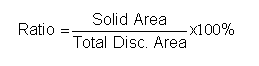
Solidity – ratio between Solid area of propeller disc ÷ Total disc Area.
Power absorption of a Propeller can be increased by increase solidity of the Propeller.
Solidity can be increased by increasing the number of Propeller blades
Stresses on a Propeller
1) Centrifugal – pulls propeller away from the hub.
2) Thrust – bending force – bends Propeller ahead in direction of the Thrust.
3) Torque – bending force acts opposite direction of rotation and places propeller behind in its plane of rotation, or it bends Propeller behind the Engine.
4) CTM – twists Propeller so as to decrease its blade angle
5) ATM – twists Propeller so as to increase its blade angle.
Usually CTM > ATM in flight
Counter Rotating Propeller – Propeller of 2 engines rotating in opposite direction & therefore No swing on Take off & No Critical engine.
Contra Rotation Propeller – Same engine has 2 sets of Propeller one rotating clockwise & other rotating anti-clockwise.
Advantages – (1) increases solidity
(2) No swing on Take off
(3) No Critical engine
Critical Engine is the engine, whose failure causes the maximum degradation of Aircraft performance.
Example- Since we know the Thrust line of the Propeller is towards the right side of a right hand moving propeller, it causes a asymmetric thrust condition to occur in a multi engine A/c with same side moving Propellers. It occurs since if in a right hand Propeller engines, the right side engine fails, the thrust line of the left hand engine which also has a right hand Propeller is towards the right side of the engine, which is nearer to the fuselage and causes a thrust line near the centre of the A/c fuselage. If in the same A/c the left engine fails, the thrust line of the live engine on the right hand side, which also has a right hand Propeller is towards right of the engine, which is farther outside from the centre of the A/c fuselage, causes a significant yaw towards left and degrades A/c performance tremendously.
In a Constant speed propeller unit, Propeller rpm is on tachometer and Engine Power setting is on manifold pressure gauge.
When propeller pitch control is moved backward (Fine to coarse) without changing the power settings the manifold press will increase.
When propeller is moved forward (Coarse to Fine) without changing the power setting the manifold press will decrease.
Therefore, when propeller is moved backward (Fine to coarse Pitch) without changing the power setting the rpm decreases, therefore, engine revolution decreases, since the fuel/air mix flow also decreases (As per Bernoulli’s principle- As the velocity decreases pressure increases).
Therefore, the manifold pressure gauge shows press decreasing.
When propeller is moved forward (Coarse to Fine) the rpm increases, therefore, engine revolution increases, since the fuel/air mixture also increases, therefore (As per Bernoulli’s principle again- As the velocity increases pressure decreases).
Therefore the manifold pressure gauge shows pressure decreasing.
When propeller rpm increases manifold pressure decreases in a CSU unit.
When propeller rpm decreases manifold pressure increases in a CSU unit
When increasing power increase rpm first by moving propeller lever forward and then manifold press in a CSU unit.
When decreasing power, decrease manifold pressure first and than decrease rpm by moving propeller lever backward in a CSU unit.
With fixed pitch propeller unit on increasing rpm increases manifold pressure as well.
Propeller driven A/c are suited for maximum altitude of 20,000 ft & maximum speed of 250-300kts
Propeller Efficiency – is calculated by the Thrust horse power produced by the propeller as compared to the Brake horse power available to the propeller.
Propeller Efficiency = T.H.P ÷ B.H.P
Pitch- is the distance in feet a propeller travels in one revolution.
Theoretical pitch/Geometric pitch- distance traveled by propeller if it was working in perfect fluid.
Practical pitch/Effective pitch- distance a propeller travels in a medium such as air.
Propeller Slip- distance between theoretical & practical pitch.
For propeller to be efficient it must have some slip.
Helix Angle- Angle between plane of rotation and relative airflow.
Propeller is more efficient at low airspeed or at low Helix angle.
High Helix angle gives lower torque.
Lower helix angle gives higher torque
Angle of Attack- Angle between chord of propeller and relative airflow.
Blade Angle- Angle between plane of rotation and chord of Propeller.
Or we can say
Blade Angle = Helix Angle + Angle of Attack.
Why A/c yaw towards left on Take off
Slipstream effect– slipstream caused by prop rotating in right hand direction tends to turn the a/c nose to the left. It occurs when the airflow meets the tail from the left side and can be corrected by offsetting the fin to the left.
- Torque effect– due to engine torque that is opposite to propeller movement, it causes extra press on the left main wheel and causes a/c to roll towards left. It is corrected by wash in on left wing (wing that tends to rise).
- Asymmetric Thrust/Asymmetric Blade Effect (On Takeoff roll occurs only on Tail Wheel A/c) (In flight occurs on any A/c in nose up attitude) The up going blade meets relative airflow at a lower angle of attack, causing a decrease in lift, therefore A/c yaws to the left. when A/c is in a nose high attitude, the down going propeller blade meets the relative airflow at a greater angle of attack as compared to the upcoming blade, therefore it produces more thrust. The up going blade meets relative airflow at a lower angle of attack, causing a decrease in lift, therefore A/c yaws to the left.
The down going blade travels more distance (right side of the propeller as viewed from the Cockpit) than the up going blade (left side of the Propeller as viewed from the Cockpit), therefore right side of the propeller produces more thrust than the left side.
This causes the a/c to swing to the left. The thrust line (mean thrust line) is not in the centre of the engine, but is slightly to the right of the engine.
- Gyroscopic effect– is mainly found in tail wheel a/c, on take off when the aircraft gains momentum, the tail rises & reflects gyro precession properties, causing the nose to yaw towards left.
A Propeller has Thrust & Torque,
Thrust is the LIFT
Torque is the DRAG
Thrust is parallel to the flight path.
Torque is along the plane of rotation.
Blade Angle is the Angle between chord & the plane of rotation of propeller.
Helix Angle is the Angle between relative airflow & the plane of rotation of Propeller.
Helix Angle is also called angle of Advance, As airspeed increases, Helix angle increases.
Blade angle = Helix angle & AOA.
Propeller pitch – is distance moved forward by the Propeller in one revolution.
The efficiency of Propeller depends upon Thrust to Torque ratio, which depends upon angle of attack therefore Propeller efficiency depends upon AOA.
Fixed pitch Propeller AOA depends upon airspeed & rpm.
It is efficient for a given particular combination of airspeed & rpm.
At high airspeed the high helix angle the T/Q ratio is low & the Propeller is less efficient.
Propeller Slip occurs when the Propeller moves forward but cannot have a grip on the air & comes back.
For the propeller to be efficient it must have some Slip.
Therefore In the Fixed pitch Propeller rpm increases on Take off run, because-
1) Propeller is at a more efficient AOA.
2) RPM increases because wind milling causes the airspeed to increase.
Therefore T/Q ratio increases.
Torque
The propeller rpm depends upon torque, which is why it does not continue to increase, it stops increasing when engine torque & engine rpm are equal.
In a fixed pitch Propeller, when nose goes down, rpm increases airspeed increases.
In a fixed pitch Propeller, when nose goes up, rpm decreases airspeed decreases.
Static rpm – is checked when A/c is stationary on the ground, by parking the A/c 90o to the wind so that the Propeller rpm is not affected by the wind milling.
Wind milling affect increases Propeller rpm on the ground.
A wind milling propeller on a failed engine gives negative thrust, causing drag.
When propeller is feathered, it goes from the fine pitch to coarse pitch to the feather position.
On Un feathering the Propeller goes to the Feather from the Course to the Fine pitch position.
Difference between a Braking Propeller & a Wind milling Propeller is that their torque moves in opposite direction.
Braking propeller gives a Positive torque.
Wind milling propeller gives a Negative torque.
In a Constant Speed Propeller oil sends Propeller to fine pitch, the Propeller goes to coarse pitch by the Speeder Springs.
If oil pressure fails, the propeller goes to the Feather position.
- Propeller at high speed suffers from compressibility error above 250kt. but compressor run at very high speed at high altitude, but does not suffer from Compressibility why.
Answer. Propeller engines are inefficient at high altitude, because as altitude increases TAS increases, temperature decreases, L.S.S. decreases. Mach no increases, and tips of Propeller reach Speed of Sound & propeller efficiency decreases. As we know the L.S.S. is a ratio of temperature & Speed of Sound.
Therefore in compressor the temperature with in the compressor are very high and L.S.S. with in the compressor is high therefore Local Speed ofSound is high.
Mach no = TAS÷ LSS
Therefore value of Critical Mach no is high, therefore compressor runs at very high speeds without being affected by the Critical Mach no.
A Shock Stall can occur at an even lower Critical Mach no in a manoeuver, like Turn etc.
A/c dives from 50,000 ft. at a TAS constant of 450 knots the IAS increases as
176 knot at 50,000 feet Mach No decreases 450/570 – 0.77
225 knot at 40,000 feet – 450/570 – 0.77
275 knot at 30,000 feet – 450/590 – 0.76
3287 knot at 20,000 feet – 450/616 – 0.73
finally 450 knot at 10,000 feet – 450/661 – 0.68
If TAS remains constant & A/c descents in a Inversion layer
Therefore in this case Mach no increases
In a Reversible Pitch Propeller, the Propeller goes to its reverse pitch position through fine & returns through Fine pitch.
To avoid hydraulic locking, the propeller should be turned through two complete revolutions in order to eject the collection of oil from the combustion chambers through the exhaust manifold & If resistance is felt in turning the propeller, it may be necessary to remove the sparking plug to drain the offending oil before the propeller can be turned.
Propeller converts mechanical energy of engine into Forward Thrust.
Propeller is acted upon 2 velocities.
1) Airspeed of A/c – Forward Velocity
2) R.PM. – Rotating Motion
Helix angle – is angle that relative airflow makes with plane of rotation.
Blade angle – is the angle that chord of propeller make with plane of rotation.
Blade angle = Helix angle + AOA.
Helix angle is also called angle of advance & depends upon airspeed of A/c. Faster the a/c higher is helix angle.
At the tip the speed is maximum, but RPM is same but distance traveled by tip from the hub is different. Tip moves faster than hub.
Because tip of the Propeller moves faster than the hub, the tip travels the greater distance than the hub in the same length of time.
Helical twist – is twisting of propeller.
A helical twist (change in AOA from hub to tip) is given to propeller so that all parts of the Propeller meet the relative airflow at the same AOA.
Propeller is fine towards the tip (blade angle is low)
Propeller is coarse towards the hub (blade angle is more).
Pitch of propeller is distance moved forward by the Propeller in one revolution.
Propeller A/c must be flow at an optimum angle of attack. Best thrust to drag ratio is at optimum angle of attack.
Fixed pitch propeller is efficient for a given combination of speed & RPM.
Pressure is high towards FACE side (towards engine side)
Feathering latches are provided to prevent Propeller feathering on the ground, when you switch off the engine they are automatically lifted and sends Propeller to the feathering position to increase drag on the Propeller and minimizes propeller rotation after engine switch off.
Auto feathering – Automatically feathers the engine whenever torque of the engine falls below a specified limit.
It feathers the propeller automatically.
If one engine is already feathered, than the other engine is not feathered automatically.
Anti-icing – To prevent ice to form.
De-icing – To remove ice that has formed.
Anti- icing spraying – Iso propyl Alcohol is used, since it decreases freezing temperature of fluid.
Stress of Propeller
1) Centrifugal
2) Thrust bending force.
3) Torque
4) CTM, Centrifugal Twisting Moment, tends to decrease blade angle.
5) ATM, Aerodynamic Twisting Moment – tends to increase blade angle.
Usually CTM is greater than A.T.M.
Therefore overall tendency is to decrease the blade angle.
Propeller Absorption – can be increase by increase the solidity of propeller
The solidity can be increased by increasing the blade no’s (Max blade numbers are 5 Max blade number of 5 are used, because high pressure on one blade will decrease the efficiency of the other blade.)
Counter Rotating propeller – one moves clockwise, the other engine propeller moves anti-clockwise.
Contra Rotating Propeller – Two sets of propeller are mounted on same engine they both moves in the opposite direction.
Contra increases solidity of the propeller