INSTRUMENT LANDING SYSTEM is a Pilot interpreted landing aid which gives vertical and azimuth guidance for the a/c to land safely under low visibility conditions. It is a standard practice followed by the airlines to follow the INSTRUMENT LANDING SYSTEM, even in clear weather as a standard procedure, since there is always a tendency of making a steep approach ending low when a visual approach is being made.
Localizer-
Range- 10° either side up to 25 N.M.
35° either side up to 17 N.M.
90° either side up to 10 N.M.
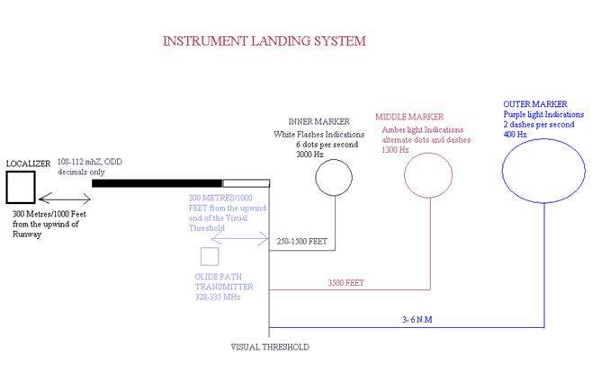
Frequency 108-112 MHz, (odd decimals only)
It is located at 300metres/1000feet, away from the upwind side of the runway (opposite to the approach end of the runway).
The principle is lobe comparison.
On approach localizer transmits two lobes, on the right side of approaching a/c (as seen from the cockpit), a 150 Hz (blue sector) is transmitted, and on the left a 90 Hz (yellow sector) lobe is transmitted, for a/c to receive equisignal of these two signals, the a/c should be accurately aligned with the runway centerline.
Maximum Localizer Deflection- 2.5° either side
Localizer 1 dot deflection in a 5 Dot Indicator causes a/c to be 50 feet away from the selected course every 1 N.M.
Glide Path Transmitter-
Range- 10 N.M.
Frequency 328-335 MHz
It is located at 300metres/1000 feet towards upwind side of the approach end of the runway, and is displaced 150metres/500 feet from the centerline towards either side of the runway.
The principle is lobe comparison.
On approach Glide path transmitter transmits two lobes, on the lower side of glide path slope which is usually 3°, a 150 Hz (blue sector) is transmitted, and on above the glide path slope a 90 Hz (yellow sector) lobe is transmitted, for a/c to receive equisignal of these two signals, the a/c should be accurately on the glide path, that guides the a/c towards the Instrument Landing Threshold that is displaced 300/metres/ 1000 feet from the visual threshold for the safety reasons.
The false glide slope always occurs above the normal Glide Slope, therefore it is always safer, since the A/c can obviously understand a false Glide slope which usually occurs above 6° of Glide Slope.
The approach plates are made in such a way that they allow the A/c to intercept the glide slope from below, eliminating the chances of A/c following or intercepting the false Glide Slope.
Standard Glide Path- 3°
Maximum Glide Slope Deflection- .7°
Markers Beacons– Frequency 75 MHz
Outer Marker– Freq 400 Hz, located at 3-6 N.M., gives Purple/Blue light indications, identification on Morse code is 2 dashes per second.
Middle Marker– Freq 1300 Hz, located at 3500 feet’s, gives Amber light indications, identification on Morse code is alternate dots &dashes.
Inner Marker– Freq 3000 Hz, located at 250-1500 feet’s, gives White Flashes light indications, identification on Morse code is 6 dots per second
Glide Path Angle = Height of A/c ×60 ÷ Distance to go in feet
The glide path of the ILS is set in a way to be aligned with the ILS threshold so that the A/c wheels touchdown on the ILS threshold, which is 1000 feet away from the visual threshold.
The A/c is made to cross the Visual threshold at a height of 50 feet.
This can be proved by the G.P Angle formula.
Height of the A/c = G.P Angle × Distance to go feet ÷60
3×1000 ÷ 60 = 50 feet
Where
Standard G.P Angle is 3°
Distance to go is 1000 feet
A thumb rule to calculate distance to start descends for approach while flying is by dividing the height by 300.
Example: maintaining Flight Level 150 (15,000 feet), airfield elevation is 6000 feet, when should you start descent to reach airfield with straight in landing instructions, 15,000-6000=9,000 feet. 9,000 ÷ 300 = 30
Therefore you should start descending when a/c is 30 N.M inbound to be able to execute a straight in landing instructions.
Rate of Descent = Glide Path Angle × Ground Speed ×100 ÷ 60 thumb rule to calculate Rate of Descent for approach while flying is by multiplying the True air speed by 120.
Example: A/c with TAS of 100 kts on approach, what rate of descent should be maintained approximately to maintain glide path angle of 3°.
100 × 120 = 1200 feet rate of descent.
INSTRUMENT LANDING SYSTEM
| Category Runway Visual Range Decision Height
1 550 METRES 200 FEET 2 350 METRES 100 FEET 3 A 200 METRES 0 FEET 3 B 50 METRES 0 FEET 3 C 0 METRES 0 FEET |
|
I LIE SOMETIMES |
Yes this can be a new name that can be given to our very own very reliable and efficient ILS.
On an incident that occurred couple of years back, it was discovered that this reliable system can give false signals and what is worse is that it does so without giving any flag warning for localizer or glide path.
Just imagine flying an ILS approach with glide path and localizer needles accurately centered and patting yourself about the good work and realizing the worth of extra session spent sweating in that hot simulator, only to discover later that the a/c has never been following the correct indications of the system.
It was discovered that removal of “Side Band”, component of the guidance signal while keeping the equipment in “TEST” will cause the carrier side band to radiate a signal that equates to “on glide slope and on course on localizer” signals in the ILS receiver that we have in the cockpit. And the worse of all is that it all happens with no warning flags, even the Morse code signal of localizer is unaffected.
Although I agree that not much can be done in this regard, and we can just hope that ATC never clears us for an ILS approach, when the facility is undergoing some maintenance work in progress.
Yeah I know you want to add that we can always cross check our position by checking heights in relation to DME distances, but as you know we don’t have DME available all over the country, and hey does your co-pilot always tells you the cross check height with relation to DME distances, if he does so, I believe it’s a very good habit to be maintained, if he doesn’t it’s time you remind him to do so.
So if you happen to be on an ILS approach next time with all the needles centered as if they are nailed to the instrument, before patting yourself, think again, it can happen because of some TEST or Maintenance being carried out at the facility.